211 Quantization box, 90, 96 Quantum boxes, 110-111, 260 Quantum dots, 111,361. 111 Quarter wave phase shift, 210 Quasi mode, 95. 276 5- polarized wave, 193 Scalar wave equation, 245 Schawlow-Townes formula, 326. Les manipulateurs sont parmi nous ebook gratuit forum. 2, 3, 17, 21 enhancement factor,% excess, 325 far-field pattern, 198 free space, 4-15 atomic.
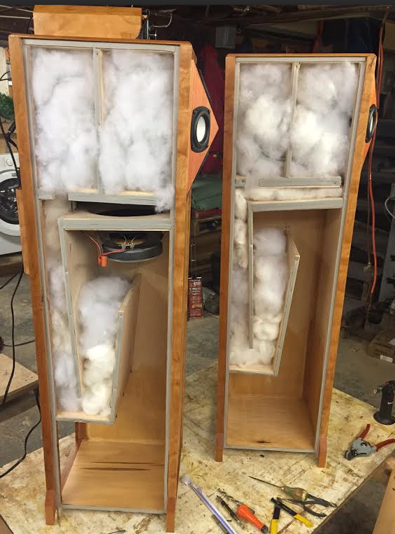
Overview: This is a calculator for designing a 1/4 Wave Flared Vent T-Line/Horn/Bass Reflex Enclosure. The formulas used in the calculator create a design that suggests the most maximally flat response in an anechoic environment based on the number of drivers, the thiele small parameters and the allotted dimensions specified in the user’s input fields. The calculator does NOT take into account the effects of placing the enclosure into the listening environment. This type of enclosure may not be the most suitable option for your application. I recommend reading the articles in the category on box design for further information.
Feel free to check out the other calculators on the site as they may provide the results you are looking for. —> You can also request a totally custom design for your driver(s)/application by filling out the form in the page. The spreadsheet calculator loads via iframe below the diagrams. You can also access the spreadsheet. Instructions: This calculator requires the input of your driver’s thiele small parameters. This design is a “driver specific” enclosure design and it is crucial to have the correct thiele small parameters for your driver(s) in order to achieve the intended alignment model from the formulas.
• Begin by filling in the input fields (white boxes) for your “Driver Specifications” in the spreadsheet. • Scroll down to the “Maximum Dimensions” section and fill in the field labeled “Material Thickness” with the width of the material you plan to use to build your enclosure out of. • Fill in the fields for the “External Height” and “External Width.” The calculator will automatically calculate the “External Depth” so take measurements of your allotted space and make sure it will all fit! • Under the “Enclosure Specifications” section, fill in in the field labeled “Chamber Depth.” This is where your driver(s) will be situated so it is advisable to compensate for its mounting depth. 3 for a clear visual as to what this dimension is.
• Now for a little trial an error! Under the “Enclosure Specifications” section, you will notice the fields labeled, “1/4 Wave Tuning Point,” “Port Frequency 1,” “Port Frequency 2,” and “Box Frequency.” In order to achieve the intended alignment model of the formulas in the calculator, you must try and get these numbers as close to the same as each other. So if the “1/4 Wave Tuning Point” is 41.5 hertz, try to get the “Port Frequency 1,” “Port Frequency 2,” and “Box Frequency” as close to 41.5 hertz too. Plus or minus 1-2 hertz is acceptable. • Use the “Port Front Width,” “Port Rear Width,” and “Port Exit Width” fields to fine tune the frequencies towards a closer match. Just keep into consideration to stay within the minimum or maximum x-sectional area recommendations for each field. • After you have finalized your design, refer to the “Panel Dimensions” section for a complete listing of panels you will need for your build.

(Panel’s dimensions are in inches.) Hint: Some of the fields in the spreadsheet may appear mislabeled. Simply click on the field and view the input bar at the top of the spreadsheet for the correct text. This page is subject to revisions. If you have any questions or comments about this calculator, feel free to send me a message using the contact form in the page.
Alternatively, for one time commercial use just send details of usage along with your donation so that a return email can be sent as proof of rights to commercial usage. 